Description
PER Meter by General Photonics
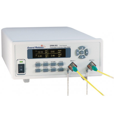
The PER Meter ERM-202 is a dual channel instrument for measuring the Polarization Extinction Ratio (Polarization Extinction Ratio PER). The second input can be PER and measuring the optical power level on components with two PM outputs in parallel. The PER Meter ERM-202 is therefore very well suited for integrated optical chips (IOC) with Y-coupler as used in fiber gyroscopes, PM coupler (PMC) and polarization beam splitter (PBC / S).
Optionally, a single-channel solution is available which can be retrofitted to 2 channels.
For each channel of the ERM-202 there is an analogue output which provides the PER measurement signal as voltage level provides. This allows the design of a control loop to automate the alignment of PM fibers.
The PER Meter ERM-202 is characterized by its large PER dynamic range of 50 dB, an angular resolution of 0.06 ° and its brilliant and high-contrast OLED display.
The instrument has 4 measuring speeds from 0.1 to 1 s / measuring cycle. PM fiber can be in the fast Align measurement mode in real time. For very accurate measurement results, the measurement time can be extended. PER, axis angle, Power level and power quotient are automatically measured and displayed in parallel on the OLED.
The PER Meter ERM-202 is an optimal solution for aligning PM fiber pigtails especially in PM fiber pigtail assembly on optical modulators, PM waveguide structures, laser diodes, fiber optic PM components such as PM coupler and beam splitter, PM fiber plug assembly, characterization of depolarizers, alignment of PM fibers before splicing, production of PM fiber coils and fiber gyroscopes.
Properties of PER Meter
- Two measuring inputs
- Simultaneous measurement of the PER and measurement of the power ratio
- PER measuring range> 50 dB
- High Contrast OLED Display
- High angular resolution
PER Meter Applications
- IOC PER and measuring the coupler division ratio
- PMC and PBS PER and measurement of the coupler division ratio
- Laser diode PM fiber pigtailing
- PM patch cord assembly
- Align PM fibers before splicing
- Quality assurance in the production of PM fiber coils and fiber gyroscopes
PER Meter Specifications
|
Wavelength Range
|
1260 to 1650 nm
|
|
Calibrated Wavelengths2
|
1550 and 1310 nm
|
|
PER Dynamic Range
|
>50 dB
|
|
PER Measuring Ranges3
|
0 ~ 50 dB for Input Power from -5 to 10 dBm
0 ~ 30 dB for Input Power from -25 to -5 dBm
|
|
PER Resolution
|
0.1 dB
|
|
PER Accuracy
|
± 0.15 dB for ER <30 dB
|
|
Angular Resolution
|
0.06 °
|
|
Angular Accuracy
|
± 1 °
|
|
Performance Measurement Accuracy
|
± 0.5 dB
|
|
Resolution of the Power Measurement
|
0.02 dBm (PER < 30 dB)
0.2 dBm (PER > 30 dB)
|
|
Input Power Measuring Range
|
-30 dBm to 10 dBm
|
|
Measurement Speed
|
0.1, 0.2, 0.4, 1 s/Polariserrotationszyklus
One Channel Version also has a 10s Measurement Cycle and a Manual Polarizer Control Mode
|
|
Connectors
|
Free space Adapter for FC Plug
|
|
Max. Optical Input Power
|
300 mW
|
|
Operating Temperature Range
|
0 bis 40° C
|
|
Storage Temperature Range
|
-20° C bis 60° C
|
|
Display
|
OLED Display
|
|
Interfaces
|
USB, RS-232, Ethernet, GPIB
|
|
Analoger Ausgang
|
0 - 5V PER analog Output Voltage for each Channel
|
|
Power Supply
|
100-240 V AC, 50-60 Hz
|
|
Dimensions
|
2U 19" half rack width, 14"(L) x 8.5"(W) x 3.5"(H)
|
Annotation:
1 Other wavelengths and plug adapters on request
2 Other calibrated wavelengths on request
3 For measurements at or slower than 0.4s / cycle


