Description
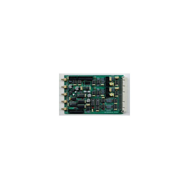
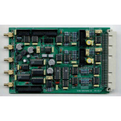
SCT-430 and SCT-441 are OEM analogue lock-in amplifiers. Both the single phase SCT-430 and dual phase SCT-441 are suitable for making amplitude and phase measurements but it is significantly easier with SCT-441. These pcb lock-in amplifiers offer a low cost solution to recovering noisy signals in many situations.
- Single and dual phase versions
- Differentialor single-ended input
- Sensitivities from 1 µV to 10 V for 1 V output
- High performance wide bandwidth input gain stage
- Low pass filter output time constants from 100 µs to 30 s
- 1F and 2F reference signal operation
- 90° step and fine phase control
A dual phase lock-in amplifier with manual setting, using jumpers, of input mode, sensitivity, low pass filter time constant and reference signal course phase control. Can be used in either of the following three modes:
Dual phase operation – one input signal with two demodulators operating 90° apart providing both X and Y (or real and imaginery) components oft he input signal.
R calculation – on board cicuitry provides the modulus of the X and Y components.
Single channel 1F and 2F operation – one input signal and two demodulators operating at 1x and 2x the reference frequency to measure the first and second harmonics oft he input signal.
- Sensitivity: 3 µV to 10 V in 1, 3, 10 steps for 1 V output (Gain settings of x 0.1 to x 330000)
- Reference input: TTL / CMOS with mark / space of 1 : 10 to 10 : 1 (triggered from rising edge only)
- Power: -15 V, 0 V, +15 V and +5 V dc at 50 mA per supply rail
Specifications
Input Signal Channels
The input signal channel amplifies the input signal to a level suitable fort he demodulator(s). High performance, low-noise, broad-band amplifiers are used throughout. The input circuits can accept differential or single-ended inputs via the input SMB connectors. Options within the unit allo the outer SMB contact or screen to act as a high impedance differential input or allow it tob e connected to ground for single-ended operation
- Input: Differential or single ended voltage via SMB socket
- Input gain: x 0,1 to x 330 in 1, 3.3, 10 steps
- Input Impedance: 12<sub>12</sub> // 1 nF, dc coupled
- Frequency: 10 Hz to 100 kHz
- Maximum Inputs: ± 10 V before saturation occurs
- Gain Accuracy: 1 %
- Gain Stability: 200 ppm / °C
- Dynamic Reserve: 0 db to 80 db
Demodulator
The input stage drives high bandwidth demodulators to recover the input signal.
Output
The demodulator outputs are passed through low pass filters before bein amplified for output.
- Output Gain: x 1, x 10, x 100, x 1000
- Low Pass Filter Time Constants: 100 µs to 30 s in 1, 3, 10 steps
- Outputs – SMB connectors: ± 100 mV to ± 10 V full scale
Reference Channel
A single reference channel is used to generate the signals that drive the demodulator(s). A fine phase shifting circuit allows the reference signal to be phase shifted from 0° to 150 ° relative tot he signal input. A second circuit then produces signals that are phase shifted by 0°, 90°, 180° and 270° at both the reference frequency and twice the reference frequency.
- Frequency: 10 Hz to 100 kHz
- Trigger: Standard TTL, mark to space ratio in the range 20:1 to 1:20. Rising edge triggered
- Acquisition Time: 10 s max
- Phase Control: 90° steps + fine shift 0° - 150°
- Phase Drift: 0.1 °/C
- 1F and 2F operation
General
- General connections are made via a 64 pin type C DIN41612 connector. Signal connections are not possible via this connector
- Mechanical: 100 x 160 mm
- Temperature Range: 0 – 50 °C
- Warranty: 2 years from date of shipment