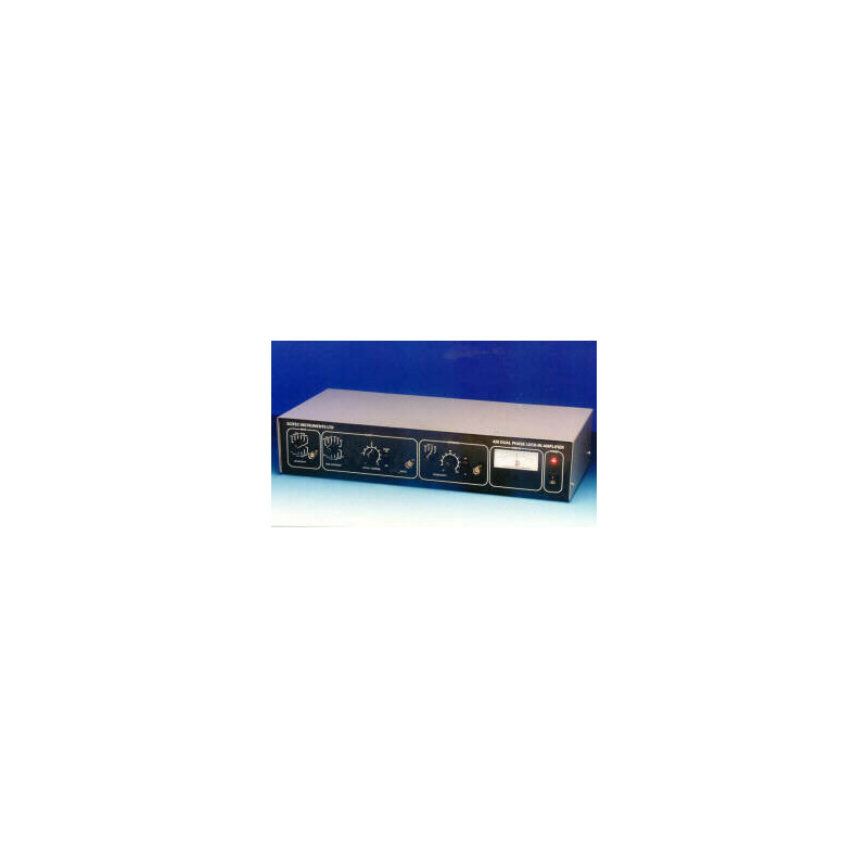
SCT-410 Lock-In Amplifier

search

Reference number: SCT-410

SCT-410 is a single phase analogue lock-in amplifier. It is suitable for making amplitude and phase measurements.

€2,232.00
Tax excluded
Quantity
Delivery

alt

Need more info?
Contact our expert.

Optics & Optomechanics Team
Phone: +49 8153 405-11

Description

  • Single phase instrument
  • Differential or single-ended input
  • Gain settings from 3 µV to 1 V
  • 10 Hz to 100 kHz
  • High performance wide bandwidth input gain stage
  • Analogue meter for display of output signals
  • Output offset controls
  • Output time constants from 100 µs to 30 s
  • 1F and 2F reference signal operation
  • 90° step and fine phase control

Lock-In amplifiers are used to measure the amplitude and phase of small AC signals in the presence of much larger noise levels. They are widely used to recover small optical signals such as those encountered in spectroscopy and studies of fluorescence and luminescence. However, they also have applications in many other fields including electronics and cryogenics where they can be used in component characterisation, bridge networks and to measure the resistance of superconductors.

The output from a l lock-in amplifier is a DC voltage proportional to the aplitude of the input signal but with the noise removed. It is also a function oft he relative phase difference between the input signal and the associated reference signal. This property allows lock-in amplifiers to be used for measuring the phase properties of the input signal as well.

Specifications

Input Signal Channel

The input signal channel amplifies the input signal to a level suitable fort he demodulator. High performance, low-noise, broad-band amplifiers are used throughout. The input circuitry can accept a differential or sigle-ended input via the front panel signal input BNC.

  • Input: High or low impedance differential or single ended via front panel BNC
  • Sensitivity: 3 µV to 1 V (for 1 V output) switched in 1, 3, 10 steps
  • Input Imedance: 10^12 W // 1 nF, dc coupled
  • Frequency: 10 Hz to 100 kHz
  • Maximum Inputs: ± 16 V before input protection circuitry comes into operation. The input BNC has been tested for electrostatic discharge damage
  • Input Noise Voltage: Other lock-in amplifier manufacturers give input noise values but without providing any definition of this specification. Indeed ther is no meaningful definition of this specification in relation to lock-in amplifiers.
  • Gain Accuracy: 1 %
  • Gain Stability: 200 ppm / °C
  • Dynamic reserve: 60 dB limited by a maximum signal input noise voltage of 10 V

Demodulator

The output of the signal input stage is processed using a very high bandwidth demodulator to recover the input signal.

Low Pass Filter

The output from the demodulator is passed through a first order low pass filter and then amplified before output via a front panel BNC.

  • Time Constant: 100 µs to 30 s in 1, 3, 10 steps
  • Output: +/-1 V output corresponds to full scale input. Short circuit protection included
  • Offset: Up to 1x full scale, switchable on or off

Reference Channel

  • Frequency: 10 Hz to 100 kHz
  • Input Impedance: 6 M ac coupled
  • Trigger: Sine - 100 mV rms min (15 V max.) Pulse - 5 V, mark to space ratio in the range 20:1 to 1:20
  • Acquisition Time: 10 s max
  • Phase Control: 90° steps + fine shift in range 0° - 100°
  • Phase Drift:1 ° / °C

General

  • Power: 115 Vac, 230 Vac; 50 - 60 Hz; 10 VA max.
  • Mechanical: 440 (W) x 87 (H) x 190 (D) mm
  • Temperature range: 0 – 50 °C
  • Warranty: 1 year from date of shipment

Standards

  • Electrostatic Discharge: BS EN 61000-4-2 Level 2
  • Surge: BS EN 61000-4-5 Level 3
  • Burst & Transient: BS EN 61000-4-4 Level 2
  • RF Emissions: BS EN 50081-2
  • RF Immunity: BS EN 61000-4-3 / BS EN 50082-2
  • Low Voltage Directive: BS EN 61010-1