Description
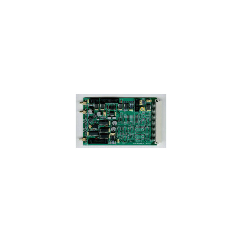
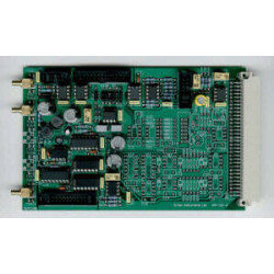
SCT-430 and SCT-441 are OEM analogue lock-in amplifiers. Both the single phase SCT-430 and dual phase SCT-441 are suitable for making amplitude and phase measurements but it is significantly easier with SCT-441. These pcb lock-in amplifiers offer a low cost solution to recovering noisy signals in many situations.
- Single and dual phase versions
- Differentialor single-ended input
- Sensitivities from 1 µV to 10 V for 1 V output
- High performance wide bandwidth input gain stage
- Low pass filter output time constants from 100 µs to 30 s
- 1F and 2F reference signal operation
- 90° step and fine phase control
A single phase lock-in amplifier with manual setting, using jumpers, of input mode, sensitivity, low pass filter time constant and reference signal course phase control.
- Sensitivity: 3 µV to 10 V in 1, 3, 10 steps for 1 V output (Gain settings of x 0.1 to x 330000)
- Reference input: TTL / CMOS with mark / space of 1 : 10 to 10 : 1 (triggered from rising edge only)
- Power: -15 V, 0 V, +15 V and +5 V dc at 50 mA per supply rail
Specifications
Input Signal Channels
The input signal channel amplifies the input signal to a level suitable fort he demodulator(s). High performance, low-noise, broad-band amplifiers are used throughout. The input circuits can accept differential or single-ended inputs via the input SMB connectors. Options within the unit allo the outer SMB contact or screen to act as a high impedance differential input or allow it tob e connected to ground for single-ended operation
- Input: Differential or single ended voltage via SMB socket
- Input gain: x 0,1 to x 330 in 1, 3.3, 10 steps
- Input Impedance: 12<sub>12</sub> // 1 nF, dc coupled
- Frequency: 10 Hz to 100 kHz
- Maximum Inputs: ± 10 V before saturation occurs
- Gain Accuracy: 1 %
- Gain Stability: 200 ppm / °C
- Dynamic Reserve: 0 db to 80 db
Demodulator
The input stage drives high bandwidth demodulators to recover the input signal.
Output
The demodulator outputs are passed through low pass filters before bein amplified for output.
- Output Gain: x 1, x 10, x 100, x 1000
- Low Pass Filter Time Constants: 100 µs to 30 s in 1, 3, 10 steps
- Outputs – SMB connectors: ± 100 mV to ± 10 V full scale
Reference Channel
A single reference channel is used to generate the signals that drive the demodulator(s). A fine phase shifting circuit allows the reference signal to be phase shifted from 0° to 150 ° relative tot he signal input. A second circuit then produces signals that are phase shifted by 0°, 90°, 180° and 270° at both the reference frequency and twice the reference frequency.
- Frequency: 10 Hz to 100 kHz
- Trigger: Standard TTL, mark to space ratio in the range 20:1 to 1:20. Rising edge triggered
- Acquisition Time: 10 s max
- Phase Control: 90° steps + fine shift 0° - 150°
- Phase Drift: 0.1 °/C
- 1F and 2F operation
General
- General connections are made via a 64 pin type C DIN41612 connector. Signal connections are not possible via this connector
- Mechanical: 100 x 160 mm
- Temperature Range: 0 – 50 °C
- Warranty: 2 years from date of shipment